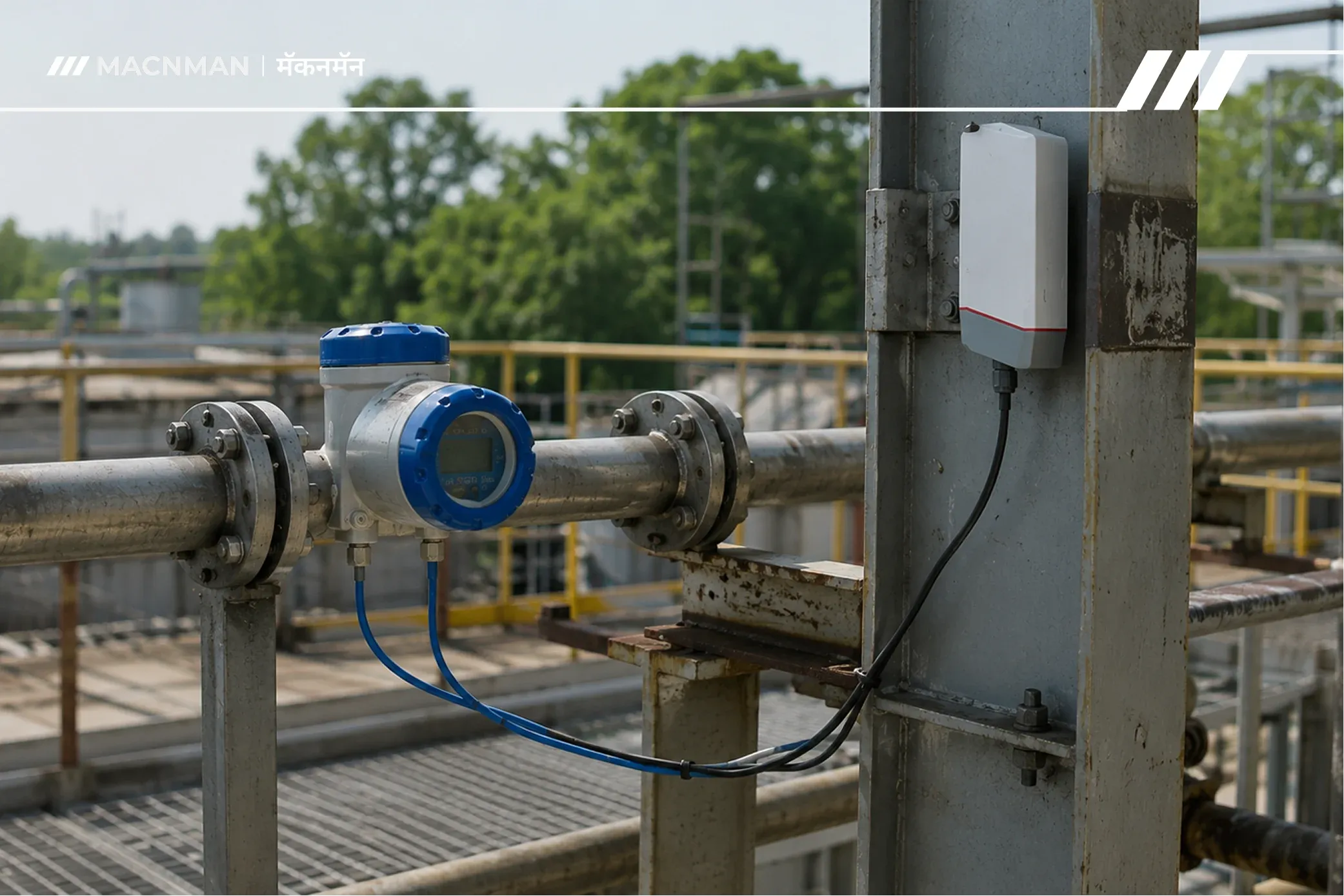
TL;DR
The Macnman 4-20mA to LoRaWAN Converter lets you connect any existing flow meter — or any other instrument — with a 4-20mA analogue output to a LoRaWAN wireless network, with no new signal cable, no civil works, and no meter replacement.
How it works: The converter clamps onto the existing two-wire 4-20mA loop from your flow meter. Its onboard 16-bit ADC samples the loop current at configurable intervals, encodes the reading into a compact LoRaWAN uplink payload, and transmits it wirelessly — up to 10 km outdoors — to a LoRaWAN gateway. The gateway forwards the data over the internet to your monitoring dashboard, cloud platform, or SCADA system.
What it replaces: Hundreds of metres of signal cable, conduit, cable trays, civil trenching, termination labour, commissioning time, and production downtime. The entire installation of the Macnman converter takes minutes — two wires from the existing loop, one antenna connection, one registration on the network server.
Who it is for: Plant engineers, facility managers, and IoT integrators who need real-time flow data from instruments already installed and calibrated in the field, without the cost and disruption of running new infrastructure to reach them.
How the Macnman 4-20mA to LoRaWAN Converter Connects Legacy Flow Meters to IoT
There are hundreds of millions of 4-20mA instruments installed in industrial facilities around the world. Flow meters. Pressure transmitters. Level sensors. Tank gauges. Temperature transmitters. Each one measuring something important, every second of every day — and transmitting that measurement down two copper wires to a control room that may be ten metres away or five hundred metres away.
Most of those instruments have been working reliably for years. Some for decades. They do not need replacing. The flow meter on your cooling water return line is measuring flow accurately and has years of service life remaining.
What they cannot do — by themselves — is get their data to a cloud platform, a remote monitoring dashboard, a SCADA system in a different building, or a mobile alert that wakes your maintenance engineer at 2 AM when flow drops below the minimum threshold.
That gap is what the Macnman 4-20mA to LoRaWAN Converter closes. Not by replacing your instruments. Not by running new cable. By sitting on the existing loop, reading the signal that is already there, and transmitting it wirelessly to wherever you need the data to go.
The Problem: Legacy Flow Meters Are Data Islands
Walk through any industrial facility built before 2015 — a water treatment plant, a chemical processing unit, a pharmaceutical manufacturing site, a large HVAC installation — and you will find flow meters everywhere. Inline electromagnetic meters on process pipes. Ultrasonic clamp-on meters on water mains. Vortex meters on steam lines. Differential pressure transmitters on orifice plates.
Every one of them is measuring flow continuously. Every one of them has a 4-20mA output. And the vast majority of them are connected to exactly one destination: a local panel display, a PLC analogue input card, or a chart recorder. Nowhere else.
The data exists. The measurement is happening. But it is trapped.
If you want that flow data in your cloud monitoring system — for trend analysis, anomaly detection, compliance reporting, or energy management — you face the same question that every plant engineer faces: how do you get the signal from that instrument to a system that can use it, without spending more on the wiring than the monitoring system is worth?
The traditional answer involves cable. New signal cable from the instrument to the nearest available network node. Conduit to protect it. Cable tray or trunking to route it. Possibly civil works — cutting into floors, walls, or external ground — to run it through the building. Termination at both ends. Testing. Documentation. And a shutdown window to do the installation without disrupting the process.
For a single instrument 50 metres from the nearest panel room, that bill comes to tens of thousands of rupees before a single data point is collected. For a facility with thirty instruments spread across a large site, the wiring cost frequently exceeds the cost of the entire monitoring software platform. And for instruments in locations where cabling is genuinely impractical — outdoor buried pipelines, remote pump stations, roof-mounted HVAC units, intrinsically safe zones — it may be technically impossible without major construction.
This is why most legacy 4-20mA instruments never get connected to modern IoT platforms. Not because the data is not valuable. Because the path to get the data out costs too much.
What Is a 4-20mA Signal? Why Every Legacy Instrument Uses It
Before explaining how the Macnman converter reads and transmits the signal, it helps to understand what a 4-20mA signal actually is — and why this standard has dominated industrial instrumentation for sixty years.
The Current Loop Principle
A 4-20mA current loop is an analogue signalling standard that represents a measurement as a proportional electrical current flowing around a two-wire circuit. The measured variable — flow rate, pressure, temperature, level — is linearly mapped across the 4 to 20 milliamp range:
| Current | Meaning |
|---|---|
| 4 mA | 0% of measurement range (zero / minimum) |
| 12 mA | 50% of measurement range (mid-scale) |
| 20 mA | 100% of measurement range (full scale / maximum) |
| < 3.6 mA | Fault / broken wire condition |
| > 20.5 mA | Over-range / fault condition |
A flow meter with a range of 0–500 m³/h transmits 4 mA when flow is zero, 12 mA when flow is 250 m³/h, and 20 mA at 500 m³/h. Any value in between is proportional.
Why 4mA and Not 0mA? The Live-Zero Principle
The choice of 4 mA as the zero point — rather than 0 mA — is deliberate and significant. It is called the live zero, and it solves a critical problem in field instrumentation: fault detection.
If the range started at 0 mA, a broken wire and a zero-flow reading would produce identical signals — 0 mA in both cases. The control system could not distinguish between the two.
With 4 mA as the live zero, any current below approximately 3.6 mA immediately indicates a fault — broken wire, failed transmitter, or disconnected instrument. The loop is "alive" even when the measurement is at zero, which is where the name comes from.
The live zero also enables loop powering: the same two wires that carry the measurement signal also power the transmitter. The instrument draws its operating power from the loop current (typically 3–10 mA of the available 4–20 mA budget) and returns the measurement as a superimposed current variation. This is why most 4-20mA field instruments need only two wires — no separate power supply cable required.
Why This Standard Has Lasted Sixty Years
The 4-20mA current loop has survived because it solves real problems that affect industrial measurements:
Immunity to cable resistance. Current is constant along a series circuit regardless of the resistance in the wire. A 200-metre cable run adds resistance, but the current reading at the receiving end is identical to the current at the transmitter. Voltage signals would degrade with distance; current signals do not.
Noise immunity. Industrial environments are electrically hostile — variable frequency drives, motors, welding equipment, and high-voltage switchgear all radiate electromagnetic interference. Current loops are inherently less susceptible to this interference than voltage signals, especially over long cable runs.
Intrinsic simplicity. Two wires, one current, one measurement. No ground loops, no common-mode noise, no impedance matching. A field technician with a clamp meter can verify signal integrity in thirty seconds.
Universal compatibility. Every PLC, DCS, SCADA system, and industrial controller made in the last five decades has 4-20mA input cards. The ecosystem is enormous and completely standardised.
This is the signal sitting on the terminals of your legacy flow meter right now. And it is exactly the signal the Macnman converter reads.
The Old Answer: Run New Cable. Why It No Longer Makes Sense
For decades, "connect this instrument to the control system" meant one answer: run cable. The economics of that answer have not aged well.
The True Cost of Industrial Cabling
When plant managers budget for a new cabling run, they typically think about the cost of the cable itself. That is the smallest part of the total.
The full cost of a new instrument cable run in an existing industrial facility includes:
Material costs:
- Signal cable (screened, armoured for outdoor/underground runs)
- Conduit or cable tray
- Glands, terminals, lugs, junction boxes
- Cable markers and documentation labels
Labour costs:
- Cable routing survey and planning
- Mechanical installation (conduit fitting, tray installation)
- Cable pulling and dressing
- Termination at both ends (instrument and panel)
- Continuity testing and insulation resistance testing
- Loop calibration and commissioning
Civil costs (if underground or through structural elements):
- Concrete or tarmac cutting
- Excavation for buried runs
- Reinstatement of surfaces after cable installation
- Structural penetration sealing (fire-rated, where required)
Operational costs:
- Process shutdown for safe installation in live areas
- Production loss during the shutdown window
- Permit-to-work administration
- Inspection and sign-off by electrical authority (for hazardous area installations)
In Indian industrial facilities, a fully-installed 100-metre screened instrument cable run typically costs between ₹40,000 and ₹1,50,000 depending on environment, routing complexity, and whether civil works are required. Outdoor underground runs, hazardous area installations (ATEX/IECEx zones), or runs through congested cable routes push the figure significantly higher.
For a facility with twenty instruments needing wireless connectivity at an average run length of 80 metres each, the cabling cost alone — before any data platform, software, or integration work — is between ₹8,00,000 and ₹30,00,000.
That is before a single dashboard has been configured or a single alert has been set.
The Instrument Replacement Alternative — and Why It Is Even More Expensive
Some IoT vendors propose replacing legacy 4-20mA instruments with native wireless smart meters. This approach has its own cost structure that plant engineers frequently underestimate:
- Procurement lead time: Specialised process flow meters have lead times of 4–16 weeks from order to delivery, depending on type and specification
- Process shutdown for installation: Replacing an inline flow meter requires isolating the line, draining the pipe, breaking the flanges, removing the old meter, installing and commissioning the new one — typically a half-day to full-day shutdown per meter on a process line
- Pipe modification: Smart meters may have different face-to-face dimensions than the existing meter, requiring spool pieces or pipe modifications
- Recalibration: A new meter must be calibrated against a known reference before it can be trusted for process measurement
- Regulatory re-approval: In metered billing, custody transfer, or regulated process applications, replacing a certified meter restarts the approval cycle with the relevant authority (Weights & Measures, process safety regulator, or customer contract requirement)
For a plant with ten certified flow meters on billing or regulatory measurement duty, replacement is not just expensive — it may not be permissible without months of regulatory process.
The Macnman 4-20mA to LoRaWAN Converter sidesteps every one of these costs. The existing meter stays in the pipe, certified, calibrated, and measuring. The converter reads its output. Nothing about the measurement itself changes.
How the Macnman 4-20mA to LoRaWAN Converter Works
The Macnman converter performs one task with high precision: it reads the 4-20mA current from your existing instrument loop and transmits that reading wirelessly over LoRaWAN. Understanding the conversion chain from end to end — from the current loop terminal to the monitoring dashboard — helps you configure, deploy, and troubleshoot it correctly.
Stage 1 — Current Loop Connection
The converter connects in series with the existing 4-20mA loop using two wires. The loop current flows through the converter's current-sensing input, where it is measured by the onboard ADC without interrupting the loop's normal operation.
Two-wire passive (loop-powered) instruments: The converter inserts into the loop between the instrument and the existing receiving device (PLC input, panel meter, or loop terminator). The loop continues to power the instrument as before; the converter reads the current without affecting the loop voltage or the instrument's operation.
Active (self-powered) transmitters: Some instruments have separate power and signal terminals. In these configurations, the converter connects across the signal output terminals. Refer to the instrument's wiring diagram to identify the signal terminals before connecting.
Loop power supply: The converter does not supply power to the loop. If the existing loop has no power source (for example, if you are connecting an instrument that was previously wired to a now-decommissioned PLC input), an external 24VDC loop power supply must be added. This is a standard field instrument power supply, widely available and low cost.
Stage 2 — ADC Sampling and Scaling
At the configured measurement interval — factory default typically 15 minutes, configurable via downlink command or commissioning tool — the converter's MCU wakes from deep sleep and commands the onboard 16-bit ADC to sample the loop current.
A 16-bit ADC resolves the 4-20mA range into 65,536 discrete steps. This gives a current resolution of approximately 0.00024 mA across the full range.
What this means for your flow measurement accuracy:
For a flow meter with a range of 0–1,000 m³/h mapped across 4–20 mA:
- Full span = 16 mA = 1,000 m³/h
- ADC resolution = 16 mA ÷ 65,536 = 0.000244 mA per step
- Flow resolution = 1,000 m³/h ÷ 65,536 ≈ 0.015 m³/h per step
The wireless conversion introduces less than 0.015 m³/h of quantisation error into a 0–1,000 m³/h measurement — a resolution that is an order of magnitude better than the accuracy of any flow meter currently in production. The analogue-to-digital conversion is not the accuracy-limiting factor in your measurement chain. The flow meter's own uncertainty specification is.
After sampling, the firmware applies the configured engineering unit scaling — mapping the raw ADC count to the physical measurement range (e.g., 0–1,000 m³/h or 0–10 bar) — and packs the result into the uplink payload.
Stage 3 — Payload Encoding and LoRaWAN Uplink
The scaled measurement value is encoded into a compact binary payload — typically 4–8 bytes for a single-channel converter — along with battery voltage and a status byte. The LoRa radio chip (typically Semtech SX1261 or SX1262) modulates this payload onto the IN865 (865–867 MHz in India) sub-GHz channel using chirp spread spectrum, and transmits it at the configured spreading factor.
The transmission itself takes 50–1,500 ms depending on spreading factor and payload size. After the transmit window and the two Class A receive windows (for any pending downlink commands), the converter returns to deep sleep, drawing microamp-level current until the next scheduled measurement.
This deep sleep architecture is what enables battery-powered operation over multi-year periods — the converter is actively consuming power for less than 2 seconds per 15-minute cycle. More than 99.7% of its operating life is spent drawing essentially nothing.
Stage 4 — Gateway Reception and Forwarding
The LoRaWAN gateway — mounted on a rooftop, mast, or wall within radio range of the converter — receives the uplink packet. It adds metadata (RSSI, SNR, channel, timestamp, gateway ID) and forwards the complete packet over its IP backhaul connection (Ethernet, cellular, or Wi-Fi) to the LoRaWAN network server.
A single Macnman gateway can receive transmissions from hundreds of converters simultaneously — across a large site, a factory complex, or a distributed water network — because LoRaWAN is a concurrent multipoint protocol. Multiple converters transmitting on different channels or spreading factors do not block each other.
Stage 5 — Network Server Processing and Payload Decoding
The network server (The Things Stack, ChirpStack, or your chosen platform) receives the forwarded packet, verifies the frame integrity using the device's NwkSKey, decrypts the payload using the AppSKey, and applies the configured payload decoder to produce clean, named JSON:
This JSON flows to your application via MQTT, HTTP webhook, or direct API — to whatever platform or dashboard you have configured as your data destination.
Stage 6 — Application Layer: Dashboards, Alerts, and Integration
The decoded flow data arrives at your monitoring application — ThingsBoard, Grafana, Node-RED, your own SCADA, or any platform that accepts MQTT or HTTP. Here, the data is:
- Stored in a time-series database with full timestamp history
- Visualised on real-time and trend dashboards
- Evaluated against configurable alert rules: if
flow_rate < 50ANDzone == "cooling_water_return"for more than 5 consecutive readings, send an alert - Exported for compliance reporting, energy audits, or billing reconciliation
- Integrated with your existing SCADA or ERP via standard protocols
The flow meter in the field knows none of this. It is still doing exactly what it was designed to do — measuring flow and outputting a 4-20mA signal. The Macnman converter simply made that signal available to a world it was never originally designed to reach.
Step-by-Step: Connecting Your Flow Meter to the Macnman Converter
What You Need
- Macnman 4-20mA to LoRaWAN Converter (with antenna)
- Access to the existing 4-20mA loop wiring at the instrument or junction box
- A LoRaWAN gateway within radio range (see our [LoRaWAN Gateway Placement Guide] for siting guidance)
- Network server account (The Things Stack free tier, ChirpStack, or your organisation's existing LoRaWAN server)
- The OTAA credentials printed on the converter (DevEUI, JoinEUI, AppKey)
Installation Steps
Step 1 — Register the device on your network server
Before powering the converter, register it on your LoRaWAN network server using the DevEUI, JoinEUI, and AppKey from the label. Configure the payload decoder for the Macnman converter (provided in the documentation or available on your network server's device repository). Set the frequency plan to IN865 for Indian deployments.
Step 2 — Identify the loop wiring
Locate the 4-20mA signal wiring at the instrument, local junction box, or marshalling panel. Identify the + (positive) and − (negative) signal terminals. Use a calibrated mA meter to verify the loop is live and the instrument is reading correctly before connecting the converter. Record the baseline reading.
Step 3 — Connect the converter in-loop
Insert the converter in series with the existing 4-20mA loop. The exact connection depends on whether the instrument is loop-powered (2-wire) or self-powered (4-wire) — refer to the Macnman wiring diagram for your specific configuration. The connection requires no modification to the existing instrument terminals; the converter's input is typically connected at a spare terminal in the junction box or via a breakout connector on the existing cable.
Step 4 — Configure engineering unit scaling
Using the Macnman configuration tool (NFC, Bluetooth commissioning app, or AT command interface depending on variant), set the measurement range to match your instrument's span. For a flow meter ranging 0–500 m³/h, set 4 mA = 0 m³/h and 20 mA = 500 m³/h. The converter will apply this scaling automatically to all subsequent uplinks.
Step 5 — Attach the antenna and power on
Connect the LoRaWAN antenna to the SMA connector. Install the battery (if battery-powered) or connect the external power supply. The converter will immediately attempt an OTAA join on the IN865 channels. A successful join is typically confirmed within 60 seconds if the gateway is in range.
Step 6 — Verify in the network server
Check the network server dashboard. The converter should appear as connected, with its first data uplink visible within 1–2 minutes of joining. Verify the decoded flow reading matches the known loop reading from Step 2.
Total installation time per converter: 15–30 minutes for a technician familiar with the instrument wiring. No civil works. No cable drum. No conduit fittings. No concrete cutting.
What Happens to Your Data: From Flow Meter to Dashboard
Once the Macnman converter is installed and transmitting, your flow data is available to any system that can receive MQTT or HTTP data from your LoRaWAN network server. The practical integrations that most deployments use:
Cloud IoT platforms: AWS IoT Core, Azure IoT Hub, and Google Cloud IoT all have native LoRaWAN integrations (or support via The Things Stack's integration framework). Flow data arrives in your cloud database within seconds of each uplink.
Open-source dashboards: Grafana connected to InfluxDB is the most common open-source stack for LoRaWAN time-series data. Node-RED is frequently used for alert logic and MQTT routing. Both are free and widely supported.
SCADA integration: Flow data can be forwarded to existing SCADA systems via Modbus TCP, OPC UA, or direct database writes — depending on your SCADA platform and the integration adapter configured at the network server or application layer. This allows the wireless flow data to appear in the same SCADA displays alongside data from hardwired instruments, with no visible difference to the operator.
Custom applications: Any application that can subscribe to an MQTT topic or receive an HTTP POST receives the flow data in standard JSON format. Building a custom monitoring dashboard, an ERP energy module, or a utility billing system on top of this data requires no special LoRaWAN expertise — the network server handles all the radio protocol complexity.
Flow Meter Types the Macnman Converter Works With
The 4-20mA standard is protocol-agnostic at the signal level. The Macnman converter works with any instrument that produces a standard 4-20mA output — it does not need to know what type of flow meter it is connected to. It reads current; the meter produces current. That is the entire interface.
In practice, this covers every major flow measurement technology in use in industry today:
| Flow Meter Type | 4-20mA Output? | Macnman Compatible? | Notes |
|---|---|---|---|
| Electromagnetic (mag-flow) | Yes — standard output | ✅ Yes | Most common in water/wastewater; 4-20mA is standard |
| Ultrasonic (clamp-on) | Yes — standard output | ✅ Yes | Portable and fixed clamp-on types |
| Vortex | Yes — standard output | ✅ Yes | Some vortex meters output pulse — use pulse input variant |
| Differential pressure / orifice plate | Yes — standard output | ✅ Yes | Connect to the DP transmitter's 4-20mA output |
| Coriolis | Yes — standard output | ✅ Yes | Multiple 4-20mA outputs; connect to primary flow output |
| Turbine (analogue output variant) | Yes — standard output | ✅ Yes | Some turbine meters output frequency; verify output type |
| Rotameter (variable area with transmitter) | Yes — standard output | ✅ Yes | - |
| Thermal mass flow (gas) | Yes — standard output | ✅ Yes | Common in compressed air and gas monitoring |
| Positive displacement (with transmitter) | Yes — 4-20mA from integral transmitter | ✅ Yes | - |
What the converter does not directly support: Flow meters that output a pulse (frequency) signal rather than 4-20mA — for example, older turbine meters with a raw pulse output, or water meters with reed switch pulse outputs. These require a pulse-input LoRaWAN converter variant, not the 4-20mA version. If you are unsure which output type your meter has, check the instrument datasheet or look at the existing wiring — a 4-20mA loop uses two wires to a current input; a pulse output typically uses two wires to a digital/frequency input and looks different on the PLC I/O card.
Industries and Applications Where This Matters Most
Water and Wastewater
Water utilities and industrial water treatment facilities typically have hundreds of flow meters spread across pump stations, treatment stages, distribution networks, and discharge points — many of them in remote or unmanned locations with no existing data infrastructure.
The Macnman converter allows each of these meters to transmit flow data to a central monitoring platform without running new communication cable to every remote site. A single LoRaWAN gateway mounted at a pump station can receive data from all meters within a 3–5 km radius simultaneously. Flow balancing, leak detection, consumption trend analysis, and regulatory reporting all become possible on meters that were previously readable only by a technician driving to the site.
Pharmaceutical and Chemical Manufacturing
Process flow in pharmaceutical and chemical plants is a critical quality parameter — the right ingredient volumes, in the right ratios, at the right flow rates, are directly tied to product quality and batch compliance. Existing certified flow meters on process lines cannot be replaced without regulatory re-approval.
The Macnman converter allows these certified meters to feed their measurements into manufacturing execution systems (MES) or quality management platforms wirelessly, without any change to the certified measurement itself. Audit trails for batch records become automated rather than manually transcribed.
Oil and Gas — Pipelines and Wellheads
Flow meters in oil and gas applications are frequently in remote locations with no communication infrastructure. Running cable to a wellhead or pipeline mid-point is a major construction project. LoRaWAN's range of 5–15 km outdoors means a single gateway at a central control point can serve dozens of remote flow points across a field.
The converter's battery-powered operation eliminates the need for power infrastructure at the instrument location — critical for truly remote sites where mains power is unavailable.
HVAC and Building Services
Large commercial buildings and industrial facilities use flow meters on chilled water circuits, heating circuits, and condenser water loops as part of their energy management strategy. These meters are often installed in basement plant rooms, roof plant areas, or ceiling voids — locations where running new data cables to a BMS server is disruptive and expensive.
A Macnman converter on each flow meter transmits data to a LoRaWAN gateway covering the entire building, making the flow data available to the BMS or energy management platform without any structural modification.
Energy Management and Sustainability Reporting
Accurate flow metering underpins energy efficiency programmes, ISO 50001 energy management systems, and ESG reporting obligations. Many facilities have the flow meters required for this reporting already installed — but the data is only available locally. The Macnman converter closes the last mile between the installed measurement infrastructure and the reporting platform.
Real Cost Comparison: Cabling vs. the Macnman Wireless Retrofit
The most compelling case for the Macnman converter is not technical — it is financial. Here is a realistic comparison for a mid-size industrial facility needing to connect 20 flow meters to a central monitoring platform.
Scenario: 20 Flow Meters Across a 2-Hectare Manufacturing Site :
Option 1: New signal cable to each instrument
| Cost Item | Per Instrument | 20 Instruments Total |
|---|---|---|
| Screened instrument cable (80 m avg) | ₹3,200 | ₹64,000 |
| Conduit and trunking | ₹4,000 | ₹80,000 |
| Cable pulling and termination labour | ₹8,000 | ₹1,60,000 |
| Civil works (where required) | ₹6,000 | ₹1,20,000 |
| Testing and commissioning | ₹2,500 | ₹50,000 |
| Production downtime (avg 2 hrs/meter) | ₹5,000 | ₹1,00,000 |
| Total — cabling approach | ₹28,700 | ₹5,74,000 |
Option 2: Macnman 4-20mA to LoRaWAN Converter :
| Cost Item | Unit | Total |
|---|---|---|
| Macnman 4-20mA to LoRaWAN Converter × 20 | ₹4000 | ₹80000 |
| LoRaWAN gateway (1 covers full site) | One-time | ₹55000 |
| Installation labour (30 min × 20 devices) | 10 hrs total | ₹15,000–25,000 |
| Network server setup | One-time | ₹0 (The Things Stack free tier) |
| Production downtime (15 min × 20) | Minimal | ₹5,000–10,000 |
| Total — Macnman wireless approach | [Device cost + ₹20,000–35,000] |
Note: Macnman converter and gateway pricing available on request. Insert your commercial pricing here before publication.
What the comparison shows:
The cabling approach costs ₹5,74,000 in infrastructure alone — before the monitoring platform, before integration, before ongoing maintenance of 1,600 metres of new cable across the site. Every time a sensor needs to be moved, the cable cost recurs.
The Macnman approach replaces that entire infrastructure spend with one gateway and twenty converters. The installation cost is a fraction of the cabling cost. The ongoing maintenance cost is near zero — the converter's battery lasts years, there is no cable to maintain, and adding a twenty-first instrument requires one additional converter and fifteen minutes of installation time, not another cable run.
For most facilities, the wireless approach pays for itself against the cabling alternative before the first data point is transmitted.
Key Specifications and What They Mean for Your Deployment
Input Specification
| Parameter | Specification | What It Means |
|---|---|---|
| Input range | 4–20 mA | Full compatibility with all standard industrial 4-20mA instruments |
| ADC resolution | 16-bit | 65,536 steps across the range; negligible quantisation error |
| Measurement accuracy | ±0.1% of full scale | Does not meaningfully degrade the connected instrument's measurement accuracy |
| Sampling interval | Configurable; typical 1–60 min | Balance between data granularity and battery life |
| Loop power supply | External (not provided by converter) | Standard 24VDC field supply required if loop has no existing power source |
| Input impedance | Low (typically 10–50 Ω) | Minimal voltage drop; does not disturb existing loop operation |
LoRaWAN Specification
| Parameter | Specification | What It Means |
|---|---|---|
| Protocol | LoRaWAN 1.0.3 / 1.1 | Compatible with The Things Stack, ChirpStack, AWS IoT Core for LoRaWAN |
| Frequency plan | IN865 (India), EU868, US915, AS923 | Specify correct plan for your region at time of order |
| Activation | OTAA (recommended) / ABP | OTAA provides rotating session keys; more secure for production deployments |
| Device class | Class A | Lowest power; downlink only after uplink; suitable for monitoring applications |
| Spreading factor | SF7–SF12 (ADR enabled) | Auto-optimised for link quality; longer range at higher SF |
| Outdoor range | Up to 10 km (line-of-sight) | Practical urban/industrial range: 1–5 km depending on environment |
| Output power | Up to +14 dBm (EU868) / +20 dBm (US915) | Regulatory-compliant per regional frequency plan |
Physical and Environmental
| Parameter | Specification | What It Means |
|---|---|---|
| Enclosure | IP65 minimum | Suitable for outdoor and general industrial environments |
| Operating temperature | −20°C to +60°C (verify with datasheet) | Covers most industrial monitoring environments |
| Power supply | Li-SOCl₂ battery / external 5–30VDC | Battery option for locations without power; external power for high-frequency sampling |
| Battery life | 3–7 years at 15-min intervals | Varies with SF, interval, and temperature — validate against your conditions |
| Antenna | External SMA; omnidirectional | Mount vertically; keep cable run short |
⚠️ Pre-publication check: Insert Macnman-specific datasheet values for all specifications above before publishing. Replace any placeholder figures with the actual product specifications.
Frequently Asked Questions
Q: Will connecting the Macnman converter affect my existing flow meter reading or the PLC input?
No. The converter connects in series with the 4-20mA loop and reads the loop current without modifying it. The existing PLC or panel meter continues to receive the same signal it always has, with no change in reading or behaviour. The converter adds a small series resistance (typically 10–50 Ω) to the loop, which may marginally reduce the loop voltage headroom — verify that the loop power supply has sufficient compliance voltage for the additional drop, particularly on loops already operating near their maximum cable resistance budget.
Q: My flow meter outputs a pulse signal, not 4-20mA. Will this converter work?
No — this converter is specifically designed for 4-20mA analogue current loop signals. Pulse-output flow meters (turbine meters with frequency output, water meters with reed switch pulse, etc.) require a pulse-input LoRaWAN converter. Contact us to identify the correct product for pulse-output applications.
Q: What LoRaWAN network server do I need?
Any LoRaWAN-compliant network server works — The Things Stack Community Edition (free for most deployments), ChirpStack (open-source, self-hosted), AWS IoT Core for LoRaWAN, or Azure IoT Hub. For Indian deployments on IN865, verify that your chosen network server is configured with the IN865 frequency plan. The Things Stack Community Edition supports IN865 out of the box.
Q: How far can the converter transmit from the flow meter to the gateway?
In open outdoor environments with the gateway antenna mounted at 10+ metres above ground, reliable transmission ranges of 3–10 km are achievable. Inside industrial buildings with concrete and steel structures, practical range is typically 300–1,500 m depending on the number and type of obstacles between converter and gateway. See our [LoRaWAN Gateway and Sensor Placement Guide] for detailed guidance on gateway siting and antenna height to maximise coverage.
Q: How often does the converter send data, and can I change it?
The default transmission interval is configurable at commissioning — common defaults are 15 or 30 minutes. The interval can be changed after deployment via a LoRaWAN downlink command from the network server, without physically accessing the converter. Shorter intervals (5 minutes) give better data resolution but reduce battery life proportionally. For applications where real-time flow monitoring is critical, external power supply enables continuous high-frequency operation without battery life concerns.
Q: Does the converter work inside a metal junction box or control panel?
The converter's radio signal is significantly attenuated by a metal enclosure. If the converter must be installed inside a metal box, use an external antenna connected to the converter via an SMA extension cable routed through a cable gland in the enclosure. The converter body can be inside the box; the antenna must be outside it with a clear path toward the gateway.
Q: Is LoRaWAN legal to use in India?
Yes. LoRaWAN operating on the IN865 frequency plan (865–867 MHz) falls under India's unlicensed spectrum allocation for Short Range Devices as per WPC (Wireless Planning and Coordination) regulations. No individual licence is required for IN865 LoRaWAN devices operating within the specified power limits. Verify current WPC regulations before deployment, as spectrum rules are subject to revision.
Q: What happens to data if the LoRaWAN network is temporarily unavailable?
The converter continues to sample the 4-20mA loop at the configured interval regardless of network availability. However, standard LoRaWAN Class A devices do not buffer failed uplinks — if the gateway is offline or out of range during a transmission, that reading is lost. For applications where data continuity during network outages is critical, select a converter variant with local data buffering capability, or specify a gateway with cellular failover backhaul. See our [LoRaWAN Gateway Placement Guide] for gateway selection guidance.
Summary: What the Macnman Converter Actually Replaces
The Macnman 4-20mA to LoRaWAN Converter is not a sensor. It does not measure flow. Your existing flow meter does that — accurately, continuously, and with whatever certification it was installed under.
What the Macnman converter replaces is the infrastructure cost of getting that measurement to a system that can use it:
| What the converter replaces | What remains unchanged |
|---|---|
| Hundreds of metres of new signal cable | Your existing flow meter and its calibration |
| Conduit, trunking, and cable trays | The existing 4-20mA loop and its wiring |
| Civil works and concrete cutting | Your PLC or panel meter (still receives the signal) |
| Electrical termination and testing labour | The measurement accuracy (16-bit ADC preserves it) |
| Production shutdown for installation | The certification status of the instrument |
| Ongoing cable maintenance | - |
The data that was already being measured — that 4-20mA signal sitting on the loop terminals of your flow meter right now — becomes available to your cloud platform, your SCADA, your energy management dashboard, and your maintenance alert system. Without a single new metre of cable.


