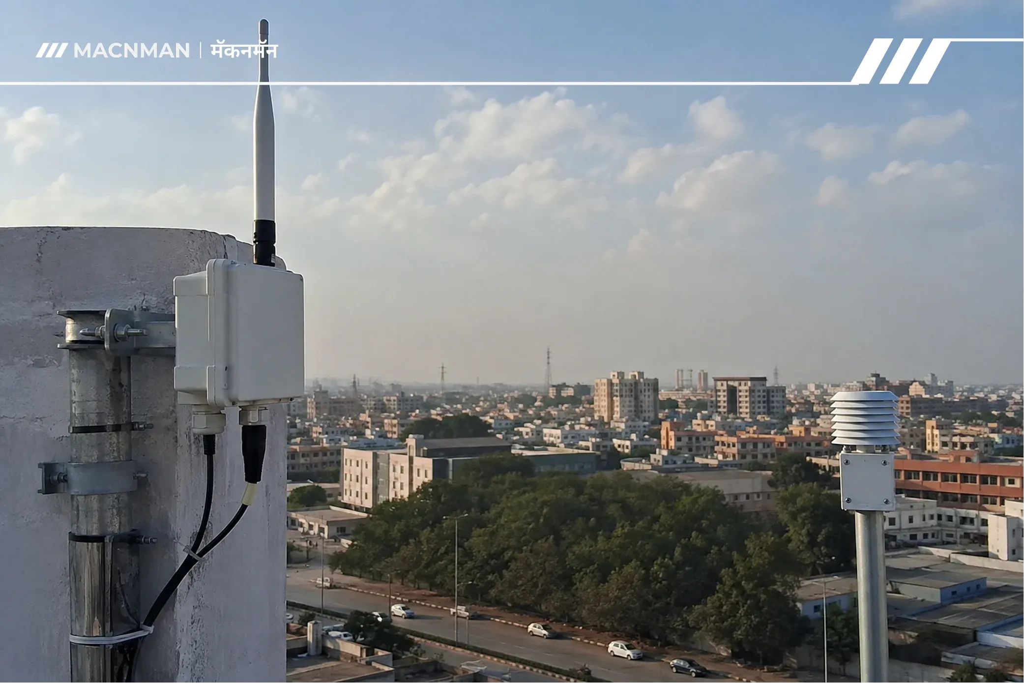
TL;DR
The single biggest variable in LoRaWAN network performance is not the gateway model or the antenna gain — it is where you mount them.
Gateway height rules:
- Outdoor rooftop: antenna tip at least 5–7 m above the roofline, on the tallest available structure
- Outdoor pole/mast: minimum 6 m above ground; 10–15 m where terrain allows
- Indoor factory/warehouse: ceiling or high wall mount, 4–8 m above floor, away from metal HVAC and steel beams
Sensor height rules:
- Outdoor environmental sensors: 1.5–3 m above ground, clear of vegetation
- Industrial floor-level sensors: as high as the process allows, minimum 0.5 m, angled away from metal equipment
- Underground/pit sensors: LoRaWAN can penetrate 1–2 concrete floors; beyond that, use a LoRaWAN Relay
Signal targets: RSSI above −100 dBm, SNR above −10 dB, packet delivery rate above 95%
Network optimization: Enable ADR for all static devices. Avoid defaulting all nodes to SF12 — it maximises range but maximises collision probability and time-on-air simultaneously.
LoRaWAN Gateway and Sensor Placement Guide: Height, Coverage, and Network Optimization
Your LoRaWAN hardware arrived. The datasheet says 15 km range. You mount the gateway, power it up, register your sensors — and half of them show RSSI of −120 dBm, two drop packets intermittently, and one in the far corner of the facility never connects at all.
The gateway is fine. The sensors are fine. The problem is placement.
This is the most consistent finding across real-world LoRaWAN deployments: the technology works exactly as specified when it is installed correctly, and underperforms badly when it is not. Range, battery life, and network reliability are all downstream of a handful of physical decisions made before a single packet is transmitted.
This guide covers those decisions in full — gateway mounting height by environment, sensor placement by use case, the physics of why height matters (Fresnel zone, cable loss, line of sight), and how to tune the network after installation for maximum efficiency.
Why Protocol Choice Is an Architecture Decision, Not a Spec Comparison
LoRaWAN's chirp spread spectrum modulation is remarkably resilient. It can decode packets at signal levels 20 dB below the noise floor — a level of sensitivity that Wi-Fi and cellular cannot approach. But that sensitivity is measured at the antenna input, not at the point where the signal leaves the ground.
Between the sensor and the gateway antenna, three physical phenomena eat your link budget:
1. Free-space path loss. Signal power falls with the square of distance. Double the distance, lose 6 dB. This is inescapable physics — but height reduces the effective distance by removing obstructions from the signal path.
2. Obstacle attenuation. Every material a LoRaWAN signal passes through costs dB. The losses are cumulative and stack fast:
| Material | Typical signal attenuation |
|---|---|
| Clear glass | 2 dB |
| Plasterboard / drywall | 3 dB |
| Brick wall (single) | 5–8 dB |
| Reinforced concrete (20 cm) | 10–15 dB |
| Reinforced concrete (30 cm) | 15–20 dB |
| Metal cladding / steel panels | 20–30 dB |
| Earth / ground (buried) | 40+ dB per metre |
A signal that passes through one concrete floor, one brick wall, and one metal equipment enclosure has already lost 25–45 dB before it travels a single metre through air. At that point, no antenna upgrade saves you — only placement does.
3. Fresnel zone blockage. This is the one that catches most deployments by surprise.
Line of sight does not mean clear signal. Even when there is a visual straight line between a sensor and a gateway antenna, any object sitting within an elliptical volume around that line — called the Fresnel zone — attenuates the signal. At 868 MHz over a 5 km link, the radius of the first Fresnel zone at the midpoint is approximately 17 metres. A rooftop parapet, a water tank, or a row of trees that appears well below the line of sight can sit inside this zone and cause significant signal loss.
The practical rule: beyond 40% blockage of the first Fresnel zone, signal loss becomes significant. For reliable links, aim to keep 60% of the first Fresnel zone clear. The only practical way to do this outdoors is height — raising the gateway antenna clears the zone without requiring you to move sensors or remove obstacles.
This is why mounting height is not a preference — it is a physics requirement.
Gateway Placement: The Core Principles
Before looking at height numbers by environment, three non-negotiable principles apply regardless of deployment type.
Principle 1: Highest Available Point, Clearest Horizon
The gateway antenna should be at the highest accessible point with the clearest unobstructed view toward the sensor population. In multi-building sites, this means the tallest roof. On a flat roof, it means a mast or weighted stand that clears the roofline — a gateway sitting flat on a roof has half its radiation pattern blocked by the building it is standing on, cutting effective coverage by up to 50%.
On towers, the elevation is usually excellent but accessibility for maintenance is poor — always validate and fully test configuration before a final tower installation.
Principle 2: Minimise Cable Length Between Gateway and Antenna
Coaxial cable is a signal killer that most deployment guides understate. At 868 MHz, a standard RG58 cable loses approximately 0.7 dB per metre. A 10-metre RG58 run costs 7 dB — more than the gain advantage of upgrading from a 3 dBi to an 8 dBi antenna. Low-loss cable (LMR-400 or equivalent) loses approximately 0.22 dB per metre at 868 MHz, making a 10-metre run cost only 2.2 dB.
The practical rule: keep coaxial cable runs as short as possible. Never exceed 10 metres on standard cable. If a long run is unavoidable, use LMR-400 or equivalent low-loss cable and factor the loss into your link budget before specifying the antenna gain.
Where possible, mount the gateway unit directly at the antenna mast with only a short tail cable, and run Ethernet or fibre for backhaul instead — Ethernet loses almost nothing over 100 metres, cable loses dB per metre.
⚠️ EIRP ceiling reminder (EU868): Adding antenna gain does not give unlimited range. The EU868 band caps EIRP at 14 dBm (25 mW) for most channels. If your gateway transmits at +14 dBm and you swap to a higher-gain antenna, you must reduce transmit power to stay compliant — the gain advantage partially cancels itself. Always account for the regulatory ceiling when planning antenna selection. See our [5 dBi vs 8 dBi antenna comparison] for a full breakdown of this trade-off.
Principle 3: Gateway Coverage Is Built Around the Sensor Population, Not the Building Layout
Start placement planning with where your sensors are, not with the most convenient gateway mounting point. A gateway centred on a building may leave sensors at the far end of a factory with marginal coverage, while a gateway at one end could reach everything with headroom to spare. Map your sensor population first; place the gateway to serve it.
Gateway Height Guide by Deployment Environment
The height numbers below are working targets based on real-world deployment data and engineering guidance from LoRa Alliance documentation and independent field studies. They are starting points, not guaranteed coverage radii — always validate with a site survey.
| Deployment Environment | Recommended Antenna Height | Coverage Radius (typical) | Key Constraints |
|---|---|---|---|
| Outdoor rural / open field | 10–30 m above ground (tower/mast) | 5–15 km | Terrain features; Fresnel zone at distance |
| Outdoor urban rooftop | 5–7 m above roofline, on tallest available building | 1–3 km | Building density; multipath; rooftop clutter |
| Outdoor suburban / industrial park | 6–10 m above roofline or on dedicated mast | 2–5 km | Trees, warehouses, varied building heights |
| Indoor factory floor | 6–8 m (ceiling mount) or high wall, above machinery | 100–500 m per gateway | Steel structure; metal machinery; EMI from VFDs/motors |
| Indoor warehouse / distribution centre | 4–6 m (ceiling mount), clear of racking | 200–600 m per gateway | Metal racking; forklift movement; roof steel |
| Indoor multi-storey building | One gateway per 1–3 floors depending on concrete thickness | Per floor: 30–100 m radius | Floor-to-floor penetration loss; elevator shafts |
| Port / rail yard / logistics hub | 10–20 m mast or gantry-mounted | 500 m–2 km | Containers (massive attenuation); mobile cranes |
| Underground / basement | Gateway above ground; relay node at transition point | 1–2 floors penetration | Each concrete floor costs 10–20 dB |
Rooftop Installation: The Most Common Mistakes
Mistake 1 — Flat-roof flush mounting. A gateway or antenna mounted directly on a flat roof has the building mass blocking the lower hemisphere of its radiation pattern. The antenna sees the sky but cannot efficiently reach sensors at ground level nearby. Always use a mast or weighted stand that clears the roofline by at least 1–2 m, and 5–7 m above the roofline for serious coverage.
Mistake 2 — High-gain antenna on a high rooftop pointed at street-level sensors. A 12–15 dBi high-gain antenna has a very narrow, flat radiation pattern. Mounted high on a tall building, it points its energy outward across the horizon — not downward toward sensors on the streets and floors below. For urban deployments where sensors are below and around the gateway, a 5–6 dBi antenna gives a wider vertical beam that serves near-field and ground-level coverage far better. Save high-gain antennas for rural deployments where sensors are far away and roughly level with the gateway.
Mistake 3 — Side-mounted antenna. An antenna mounted sideways against a wall instead of vertically has half its pattern blocked by the wall. This only works if every sensor is on the unobstructed side. In practice, it reduces effective coverage by approximately 50%.
What Kills Gateway Signal: Materials, Obstacles, and Cable Loss
The Cumulative Loss Problem
Every obstacle between a sensor and the gateway antenna adds attenuation that compounds. A device in a factory trying to reach a rooftop gateway might pass through:
- Metal roof cladding: −25 dB
- Concrete mezzanine floor: −15 dB
- Steel storage racking: −10 dB
- Distance attenuation over 300 m: −25 dB (roughly, at 868 MHz)
Total path loss: ~75 dB — all before the signal reaches the antenna. Whether the link closes depends on the link budget: transmit power + antenna gains − all losses. A typical LoRaWAN link budget with a competent gateway and SF12 is around 157 dB. Subtract 75 dB of path loss and you have 82 dB of remaining margin — which sounds like plenty until you add multipath fading, interference, and cable loss.
The point: obstacle attenuation is cumulative and real. Gateway height reduces the number of obstacles the signal has to penetrate by replacing indoor paths with outdoor air paths.
Interference Sources in Industrial Environments :
Industrial sites introduce RF interference sources that residential and urban deployments rarely face:
- Variable Frequency Drives (VFDs) and motor drives radiate broadband noise in the sub-GHz bands
- Welding equipment generates strong impulsive RF interference
- Overhead cranes and moving metal create dynamic signal shadows that change as equipment moves
- Adjacent LoRaWAN or ISM-band equipment from neighbouring facilities can cause co-channel interference on EU868
The symptom of interference is often misread as a coverage problem: RSSI looks acceptable but SNR is poor and packet loss is high. If RSSI is above −100 dBm but SNR is near 0 or negative, suspect interference rather than coverage — these two conditions have different fixes.
Sensor Placement: The Part Most Deployments Get Wrong
Gateway placement gets most of the attention. Sensor placement gets almost none — and this is where a significant fraction of real-world LoRaWAN performance failures originate.
A sensor at 0.3 m above a concrete floor, surrounded by steel machinery, trying to reach a gateway 300 m away through two walls, is fighting every variable simultaneously. Raising that same sensor to 1.5 m, orienting the antenna vertically, and positioning it on the machine's outer face rather than inside the enclosure can recover 10–15 dB of link margin with no change to any hardware.
The Core Sensor Placement Rules :
Rule 1 — Vertical antenna orientation. LoRaWAN omnidirectional antennas are designed to radiate horizontally when held vertically. An antenna lying on its side or mounted horizontally loses most of its intended gain pattern. Keep sensor antennas vertical wherever physically possible.
Rule 2 — Distance from metal surfaces. Metal detuning and reflection effects are strongest within 20 cm of a metal surface. Mount sensors at least 20 cm from any metal wall, machine body, or enclosure panel. Where the sensor must be inside a metal enclosure, use an external antenna routed out of the enclosure with a short pigtail.
Rule 3 — Height above floor. Ground-level placement is the worst-case scenario. The floor (especially concrete) absorbs and reflects signal, the antenna has no horizon clearance, and any obstacle between the sensor and gateway completely blocks the path. Even raising a sensor from 0.3 m to 1.5 m consistently improves RSSI in real-world deployments.
Rule 4 — Proximity to gateway. Sensors within 15–20 m of the gateway can cause receiver saturation issues. Keep sensors at least 15 m from any gateway. This is a near-field effect, not a coverage issue.
Rule 5 — Avoid placing sensors in corners. Corners concentrate multipath reflections from three surfaces simultaneously. Sensors mounted in room corners often show highly variable RSSI and elevated packet loss even when close to the gateway.
Sensor Height Guide by Use Case
| Sensor Type / Use Case | Recommended Mounting Height | Placement Notes |
|---|---|---|
| Outdoor environmental (temperature, humidity, air quality) | 1.5–3 m above ground | Clear of vegetation; away from heat sources and direct sunlight; antenna vertical |
| Outdoor asset tracking (poles, bollards, street furniture) | 0.5–2 m (often fixed by asset) | Use external antenna if sensor body is inside metal enclosure |
| Industrial process sensor (tank, pipe, conveyor) | As high as process allows; min 0.5 m from floor | Mount on outer face of machinery; external antenna if inside metal housing |
| Indoor factory floor monitor | 1.5–4 m (wall or column mount) | Away from VFDs, motors, and welding zones; avoid metal enclosures |
| Smart meter (electricity, water, gas) — surface mounted | Fixed by meter location; use external antenna if behind metal door | LPG/gas meters inside metal cabinets often need external antenna on cabinet exterior |
| Smart meter — pit / underground | Fixed by pit location | LoRaWAN penetrates 1–2 concrete floors; deeper requires LoRaWAN Relay (TS011) |
| Smart parking sensor (in-ground) | Flush with road surface | Designed for this use case; gateway must be higher to compensate |
| Agricultural / field sensor (soil, crop) | 0.3–1.5 m above soil | Antenna pointing up; clear of dense crop canopy where possible |
| Cold chain / refrigerated unit sensor | Inside unit — external antenna through wall gland | Metal refrigerator body completely blocks internal antenna |
| Structural health monitor (concrete, bridge) | Embedded or surface-mounted; antenna external | Surface-mount with external antenna for best results; embedded sensors need relay |
How to Plan Your Gateway Count and Coverage Overlap
A single gateway can theoretically receive packets from thousands of sensors. In practice, gateway count is driven by coverage geography and signal margin — not device count for most industrial deployments.
The Coverage Overlap Principle :
A gateway that just barely covers a sensor has no margin for environmental variation — temperature changes, seasonal vegetation growth, a new piece of equipment moved into the path. For production deployments, plan for 20–30% coverage overlap between adjacent gateways so that every sensor can reach at least two gateways simultaneously.
This overlap also gives you:
- Redundancy — if one gateway goes offline, sensors continue operating via the second
- Geolocation capability — multi-gateway reception enables TDOA-based device location without GPS
- SF diversity — a device that switches to a higher SF (lower data rate, longer range) when conditions degrade can still reach a second gateway on a different spreading factor
Gateway Spacing Rules of Thumb
These are planning estimates — always verify with a site survey:
| Environment | Suggested Gateway Spacing (with 20–30% overlap) |
|---|---|
| Open rural / agricultural | 8–12 km between gateways |
| Suburban / mixed use | 3–5 km |
| Dense urban | 1–2 km |
| Large outdoor industrial site | 1–3 km (depends on structures) |
| Indoor factory (single floor) | 100–300 m (one gateway per large area) |
| Indoor warehouse (tall ceiling) | 150–400 m |
| Multi-storey building | One gateway per 1–3 floors |
When to Add a Gateway vs When to Adjust Placement
Adding a gateway is not always the answer. Before increasing gateway count:
- Check antenna orientation — is it truly vertical? Is the cable intact and undamaged?
- Check cable loss — has someone added a cable extension that was not in the original plan?
- Move the existing gateway — even a 2–3 m change in position can make a dramatic difference in a factory environment
- Check sensor placement — is the problem sensor mounted against metal, in a corner, or at floor level?
If the issue persists after optimising these variables, then add a gateway or a LoRaWAN Relay node for coverage extension into a dead zone.
Network Optimization: ADR, Spreading Factors, and RSSI/SNR Targets
Hardware placement determines whether a signal arrives. Network configuration determines whether the network uses that signal efficiently. These two are independent — excellent placement with poor configuration wastes the advantage.
Understanding Spreading Factors :
LoRaWAN uses spreading factors (SF7 through SF12) to trade data rate against range and receiver sensitivity:
| Spreading Factor | Approximate Range (open outdoor) | Data Rate (typical, 125 kHz BW) | Time on Air (50-byte payload) | Battery Impact |
|---|---|---|---|---|
| SF7 | ~2 km | ~5.5 kbps | ~56 ms | Lowest |
| SF8 | ~4 km | ~3.1 kbps | ~103 ms | Low |
| SF9 | ~6 km | ~1.8 kbps | ~185 ms | Moderate |
| SF10 | ~8 km | ~0.98 kbps | ~370 ms | High |
| SF11 | ~11 km | ~0.54 kbps | ~741 ms | Higher |
| SF12 | ~15 km | ~0.29 kbps | ~1,483 ms | Highest |
Note : Ranges are approximate under open-field, line-of-sight conditions. Urban and indoor ranges are significantly shorter.
The SF12 over-reliance trap
The SF12 over-reliance trap is one of the most common network configuration mistakes. Defaulting all devices to SF12 maximises range per device but simultaneously maximises time-on-air per transmission. In a network with many devices, long time-on-air from every device means:
- Higher collision probability (two devices transmitting on the same channel at the same time)
- Higher aggregate duty cycle consumption
- Lower effective network capacity
A documented real-world example: in a smart parking deployment, using SF10 for all nodes produced a 37% uplink collision rate during peak hours. After switching to dynamic SF selection based on measured RSSI (SF7 for RSSI > −80 dBm, SF9 for −100 to −80 dBm, SF10 only below −100 dBm), the collision rate dropped below 9%.
Use the lowest spreading factor that maintains a reliable link, not the highest one that might cover the distance.
Adaptive Data Rate (ADR)
ADR is the LoRaWAN network server's mechanism for automatically optimising spreading factor and transmit power per device based on measured link quality. When enabled, the network server monitors the RSSI and SNR of each device's last 20 transmissions, then instructs the device to reduce its SF (and therefore its time-on-air) if the signal quality is better than required.
Key facts about ADR that most posts omit:
- ADR requires 20 uplink packets to converge on an optimised SF. For a device transmitting once per hour, that is 20 hours of deployment before ADR has tuned the connection. Do not judge network performance in the first day of operation.
- ADR is appropriate for static devices only. For mobile devices (trackers, wearables), ADR struggles because link quality changes faster than the 20-packet convergence window. Disable ADR for mobile devices and set SF manually based on expected link conditions.
- Different network servers implement ADR differently. The Things Stack v3, ChirpStack, and AWS IoT Core for LoRaWAN all use the same underlying algorithm but may have different default thresholds and convergence speeds. Check your network server's specific documentation.
- ADR reduces transmit power as well as SF where possible — this directly extends battery life for devices that were over-transmitting due to poor initial configuration.
Enable ADR for every static device in your network. It costs nothing and consistently improves both battery life and network capacity.
RSSI and SNR Target Values
These are the signal quality metrics you read from your network server's device view. Use them to assess placement quality and diagnose problems:
| Metric | Excellent | Good | Marginal | Poor / Action Required |
|---|---|---|---|---|
| RSSI | > −80 dBm | −80 to −100 dBm | −100 to −115 dBm | < −115 dBm |
| SNR | > +5 dB | 0 to +5 dB | −10 to 0 dB | < −10 dB |
| Packet Delivery Rate | > 99% | 95–99% | 85–95% | < 85% |
How to read combined RSSI + SNR:
- Good RSSI, poor SNR (e.g., RSSI −85 dBm, SNR −8 dB): The signal is strong but noisy. This typically indicates local RF interference — a VFD, adjacent LoRaWAN traffic, or broadband noise source near the gateway. Moving the gateway, adding filtering, or relocating away from the noise source is the fix. A new gateway location will not help.
- Poor RSSI, good SNR (e.g., RSSI −110 dBm, SNR +3 dB): The signal is weak but clean. This is a coverage/distance or obstacle problem. Better gateway height, a shorter cable run, or a higher-gain antenna (if within EIRP limits) will help.
- Poor RSSI, poor SNR: Both distance and interference are problems. Address placement first, then re-evaluate interference.
Channel Planning for Dense Deployments
In deployments with multiple gateways and high device density, channel planning prevents unnecessary interference between your own infrastructure:
- In EU868, use the full set of 8 default channels across gateways rather than concentrating traffic on 3. Most gateway firmware does this automatically, but verify.
- In deployments where gateways are within 500 m of each other, plan non-overlapping channel assignments to reduce co-gateway interference.
- In US915, use sub-band planning to divide the 64 uplink channels across gateway zones.
The Site Survey Process: Before You Mount Anything
Every professional LoRaWAN deployment begins with a site survey. Skipping it is the most expensive shortcut in IoT infrastructure.
Step 1 — Map the Sensor Population
Before selecting a gateway location, mark every planned sensor position on a floor plan or site map. Note mounting height, surrounding materials, and any significant metal structures or interference sources near each sensor. This map drives every subsequent decision.
Step 2 — Candidate Gateway Locations
Identify 2–4 candidate gateway mounting locations that are: elevated above the main sensor population, accessible for installation and maintenance, have power and backhaul available (Ethernet, or cellular if using a cellular-backhaul gateway), and are not adjacent to known interference sources (VFDs, high-power electrical panels, generator rooms).
Step 3 — Temporary Gateway and Walk Test
Mount a temporary gateway at the best candidate location. Use a LoRaWAN test device (or a configured sensor node) to walk the site and record RSSI and SNR at each planned sensor position. Most network servers show this data in real time. Record every reading — do not rely on memory.
Tools useful for this stage: Semtech's LoRa Cloud coverage mapper, ChirpStack's built-in device dashboard, or a dedicated LoRaWAN field tester. A "canary node" — a test device placed at the planned sensor location — is the most representative method.
Step 4 — Identify Dead Zones and Marginal Coverage Areas
Anywhere RSSI falls below −110 dBm or SNR below −10 dB is a dead zone risk. Anywhere in the −100 to −115 dBm range is marginal and will degrade further as the environment changes (new equipment added, temperature effects on building materials, seasonal vegetation growth outdoors).
For each dead zone, evaluate: can gateway height be increased, can cable loss be reduced, or does a second gateway or relay node need to be placed?
Step 5 — Finalise Gateway Position and Validate
Move the gateway to its final position (ideally slightly different from the test position based on survey findings) and repeat the walk test. Validate every sensor location before any sensor is permanently installed.
This process adds one to two days to a project but eliminates the most expensive class of rework: swapping hardware and re-running cable after the sensors are already mounted in place.
Common Placement Mistakes and How to Fix Them
| Mistake | Symptom | Fix |
|---|---|---|
| Gateway on flat roof without mast | Sensors on one side work; other side has marginal coverage | Add weighted mast to clear roofline by 2–5 m |
| Long coaxial cable run (>5 m RG58) | Coverage radius smaller than expected; RSSI lower than calculated | Replace with LMR-400; shorten run; move gateway to antenna mast |
| High-gain antenna on tall building pointing at nearby sensors | Sensors close to the building have poor signal; distant sensors are fine | Switch to 5–6 dBi omnidirectional antenna; high-gain is wrong for near-field |
| Sensor inside metal enclosure, internal antenna only | Device never connects or drops constantly | Add external antenna via SMA pigtail through enclosure gland |
| Sensor at floor level near heavy machinery | RSSI marginal; SNR poor; packet loss high | Raise sensor to 1.5 m minimum; mount on exterior face of machinery |
| Gateway near VFD or motor drive panel | RSSI acceptable but SNR near 0; packet loss high | Relocate gateway at least 5 m from EMI sources; consider adding band-pass filter |
| All devices set to SF12 | Network functions but capacity is poor; collision rate rises | Enable ADR or manually profile devices with dynamic SF selection based on RSSI |
| Gateway in equipment room / basement | Coverage severely limited despite strong hardware | Move gateway to highest accessible point with clear line of sight |
| Sensor antenna not vertical | RSSI lower than adjacent sensors in same location | Reorient antenna to vertical; re-test |
| Multiple gateways too close together with same channel config | Packet loss increases with device count | Add channel diversity; verify non-overlapping channel assignments across gateways |
Frequently Asked Questions
Q: How high should a LoRaWAN gateway be mounted outdoors?
For outdoor deployments, mount the gateway antenna at least 5–7 metres above the roofline of the building it is installed on — and always on the tallest available structure in the area. For pole or mast installations, 10–15 metres above ground is the practical target in most environments. The objective is to place the antenna above the majority of surrounding obstacles so that the Fresnel zone between the gateway and distant sensors stays clear. In open rural environments where sensors are far away and at ground level, gateway heights of 20–30 m on dedicated towers deliver the best coverage.
Q: What height should LoRaWAN sensors be mounted at?
The optimal sensor mounting height depends on the use case and environment. General rule: as high as the application allows, with a minimum of 1.5 m above the floor or ground in most indoor deployments. Outdoor environmental sensors work well at 1.5–3 m. Industrial sensors on machinery should be mounted on the outer face of equipment, as high on the unit as the process allows, and never inside metal enclosures without an external antenna. Ground-level placement (below 0.5 m) should be avoided wherever possible — the floor reflects and absorbs signal, eliminating the horizon clearance the sensor antenna needs.
Q: How far apart should LoRaWAN gateways be placed?
Gateway spacing depends entirely on the environment. In open rural areas, 8–12 km between gateways is achievable with well-sited antennas. In dense urban areas, 1–2 km is more realistic. Inside industrial facilities, one gateway typically covers 100–500 m depending on building structure and machinery density. Always plan for 20–30% coverage overlap between adjacent gateways so sensors can reach at least two gateways simultaneously — this provides redundancy and improves reliability.
Q: What is a good RSSI value for LoRaWAN?
RSSI above −100 dBm is the working minimum for a reliable LoRaWAN link. Values above −80 dBm are excellent. The range between −100 and −115 dBm is marginal — the link will function but may degrade with environmental changes. Below −115 dBm, packet loss becomes likely and the link is not reliable for production use. Note that RSSI alone does not tell the full story — always check SNR alongside it. An RSSI of −85 dBm with an SNR of −8 dB indicates an interference problem, not a coverage problem.
Q: What is a good SNR value for LoRaWAN?
SNR above 0 dB is good. SNR between −10 dB and 0 dB is marginal. Below −10 dB the link is unreliable at most spreading factors. Unlike most radio technologies, LoRaWAN can decode signals with negative SNR — the chirp spread spectrum modulation allows the gateway to pull the signal out of the noise floor. However, the SNR threshold for reliable decoding depends on the spreading factor: SF7 requires SNR above approximately −7.5 dB, while SF12 can decode signals down to approximately −20 dB SNR. This is why ADR matters — choosing the right SF for the measured SNR ensures reliable decoding with minimum time-on-air.
Q: Should I enable ADR (Adaptive Data Rate) on all my LoRaWAN devices?
Enable ADR on all static (non-moving) devices. ADR allows the network server to optimise spreading factor and transmit power based on measured link quality, improving battery life and network capacity simultaneously. The only devices that should not use ADR are mobile ones — trackers, wearables, or equipment that moves between locations — because ADR's 20-packet convergence window is too slow for rapidly changing link conditions. For mobile devices, either set a fixed SF appropriate to the expected worst-case link, or implement custom adaptive logic at the application layer.
Q: Can LoRaWAN signals reach underground or buried sensors?
Yes, with limitations. LoRaWAN's sub-GHz frequency and chirp spread spectrum modulation give it better-than-average penetration into sub-surface environments. In practice, the signal can penetrate 1–2 concrete floors below grade before the link becomes unreliable. For sensors embedded deeper — in buried chambers, utility tunnels, or multi-level basements — the LoRaWAN Relay specification (TS011, standardised 2022–2023) provides a standards-compliant solution: a low-power relay node is placed at the surface or transition point, passing packets from the underground sensor to the above-ground gateway.
Q: How long does it take ADR to optimise a LoRaWAN device?
ADR converges after the network server has received 20 consecutive uplinks from the device. For a device transmitting once every 10 minutes, that is approximately 3.3 hours. For a device transmitting once per hour, it is 20 hours. For a device transmitting once per day, full ADR convergence takes 20 days. During this convergence period, the device operates at whatever SF was configured at join — which is often SF7 (default on many devices) or SF12 (manually set during testing). Verify your device's initial SF setting matches what is appropriate for its link quality before deployment to avoid either unreliable links (SF too low) or unnecessary channel occupancy (SF too high) during the convergence window.
Q: How many sensors can one LoRaWAN gateway handle?
A single LoRaWAN gateway with an 8-channel packet forwarder can theoretically support 1,000–5,000 sensors, depending on uplink frequency and spreading factor distribution. In practice, the real limit in dense deployments is collision probability rather than gateway processing capacity: too many devices transmitting at the same time on the same channel and SF creates packet collisions that neither the gateway nor the sensors can resolve. Managing SF distribution (using ADR or manual profiling), spreading device uplink timing with random jitter offsets, and splitting high-density deployments across multiple gateways are the standard mitigations. For single-channel gateways: note that single-channel packet forwarders are deprecated on The Things Stack v3 and no longer functional on The Things Network — see our [single vs multi-channel gateway comparison] for details.


