LoRa Door Sensor Configuration Guide
1. Device Naming
- Open Name field
- Enter new name
- Save

Recommendation:
Use location-based naming (e.g., Warehouse-Door-01) for clarity.
4. LoRa Communication Settings
Go to LoRa Settings and verify parameters.
All settings must match: Sensor ↔ Gateway
Required Parameters
-
Class → Must match
-
Frequency (IN865) → Standard band in India
-
Spreading Factor (SF)
- Lower SF → Faster transmission, shorter range
- Higher SF → Slower transmission, longer range
-
Channel → Must be identical
-
Slave ID → Unique per device
-
Encryption Key → Must match for secure communication
Purpose:
Ensures stable and secure wireless communication.
How to change LoRa Class? :

LoRa Class
Select the appropriate LoRa Class based on your device’s power source and application needs:
-
Class A
Recommended for battery-powered devices. It offers the lowest power consumption and is suitable for sensors that transmit data occasionally. -
Class C
Designed for mains-powered devices. It keeps the receiver always on, allowing near-instant downlink communication from the server.
Choosing the correct class helps optimize battery life and network responsiveness based on your deployment.
Controller are available in the Class C mode only
LoRa Frequency

Select the appropriate LoRa frequency band based on your deployment region and local regulatory standards.
- Example
IN865(India),IN868(Europe),US915(North America)
LoRa SF
How to LoRa Spreading Factors ? :
Inside LoRa settings, navigate to SF (Spreading Factor) and toggle up and down as per requirement.

LoRa Channels
How to setup LoRa channels ? :
Inside LoRa settings, navigate to channels and type in channel number as per requirement.

Slave ID
How to setup device slave ID ? :
Inside LoRa settings, navigate to Slave ID and type in Slave ID number as per requirement.

Encryption Key
How to setup device Encryption Key ? :
Inside LoRa settings, navigate to Encryption Key and type in Encryption Key number as per requirement.

3. Network Capacity
- Up to 20 devices per gateway
- Recommended at 5-minute uplink interval
Note:
Higher transmission frequency can reduce supported device count.
4. Viewing Sensor Data
Go to: Device Data
You can monitor:
- Door Status
- Door Cycle Count
- Battery Status
Status Values
0→ Door Closed1→ Door Open

Purpose:
Provides real-time monitoring of door activity.
5. Modbus Data Reading (Advanced)
To read data via Modbus:
- Connect gateway to PC using RS485 converter
- Use the following parameters:
| Parameter | Value |
|---|---|
| Slave ID | 6 |
| Function Code | 4 |
| Address | 0 |
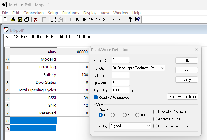
Purpose:
Allows integration with external systems or software for data logging.